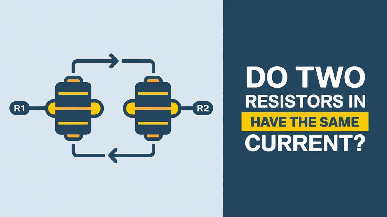
In a series circuit, the current flow is the same across all resistors. This means that when two resistors are connected in series, the current through each is the same. This principle is key to understanding series circuits and is important for working with resistors in electrical applications.
The total resistance of resistors in series is found by adding their individual resistances. This helps in figuring out the current flow in the circuit. For engineers and technicians, knowing this is essential. It lets them calculate the voltage drop across each resistor using Ohm’s law. They can also find out the power dissipated by each resistor in the series circuit.
Basic Principles of Series Circuits
Series circuits are key to understanding electrical current and circuit properties. In a series circuit, components are connected one after the other. This lets the same current flow through each part.
This setup makes it easy to figure out the total resistance, voltage drop, and power dissipation. It’s all about the flow of electricity.
In a series circuit, the total resistance is the sum of each resistance. You can find the voltage drop across each resistor with Ohm’s law. The power lost by a resistor is calculated as P = I^2 * R, where I is the current and R is the resistance.
Definition of Series Connection
A series connection means components are linked one after the other. This lets the same current flow through each part. It’s vital for understanding circuit properties and calculating electrical current.
Current Flow Fundamentals
In a series circuit, the current stays the same everywhere. It doesn’t change or add up at different spots. You can easily find the current using the battery voltage and resistance values.
Properties of Series Circuits
Series circuits have unique properties. One is the idea of equivalent resistance, which makes analysis easier. The resistor with the highest resistance has the biggest voltage drop. Ohm’s law is key in figuring out voltage drops across resistors in series circuits.
Some important things to remember about series circuits are:
- The total resistance of resistors in series is the sum of the individual resistances.
- The voltage drop across each resistor in a series connection can be calculated using Ohm’s law.
- The power dissipated by a resistor in a series circuit is given by the formula P = I^2 * R.
Current Behavior Through Series Resistors
In a series circuit, the current stays the same everywhere. It depends on the total resistance and the voltage applied. This is because the total resistance is the sum of all resistances in series.
Ohm’s law controls how resistors behave in series circuits. It says current is directly related to voltage and inversely to resistance. So, the same current flows through each resistor, and the total voltage drop is the sum of each resistor’s drop.
Some key things about series circuits are:
- The current through each resistor is the same
- The total voltage drop is the sum of each resistor’s drop
- The total resistance is the sum of all resistances
These points help us understand how current works in series circuits. They also show how resistors behave under these conditions.
| Characteristic | Description |
|---|---|
| Current Distribution | Uniform current distribution, with the same amount of current passing through each resistor |
| Resistor Behavior | Governed by Ohm’s law, with the current through each resistor directly proportional to the voltage across it and inversely proportional to the resistance |
| Total Voltage Drop | Equal to the sum of the voltage drops across each resistor |
Ohm’s Law Application in Series Circuits
Ohm’s Law is key in series circuits. It shows how voltage, current, and resistance are linked. The total resistance is the sum of all resistances, impacting the current flow. The voltage drops across each resistor are in proportion to its resistance, adding up to the total voltage.
Voltage Distribution Across Resistors
In series circuits, the voltage on each resistor depends on its resistance. A resistor with higher resistance will have a bigger voltage drop. For instance, with resistors of 2 kΩ, 4 kΩ, and 6 kΩ, the total resistance is 12 kΩ. Using Ohm’s Law, we can find the voltage drops across each one.
Total Resistance Calculation
The total resistance of a series circuit is the sum of all individual resistances. Here’s a table showing how it works:
| Resistor Value | Total Resistance |
|---|---|
| 2 kΩ + 4 kΩ + 6 kΩ | 12 kΩ |
| 2 ohms + 2 ohms + 3 ohms | 7 ohms |
Current Measurement Methods
Getting the current right is vital for circuit performance. Ohm’s Law helps calculate the total current. Kirchhoff’s Voltage Law lets us check the voltage drops. Knowing these, engineers can improve circuit design and ensure it works well.
Physical Properties of Series-Connected Components
When components are connected in series, their physical properties are key. These properties, like resistance values, affect how much power and heat each component generates.
Power dissipation in a resistor is directly tied to its resistance value. This means that components with higher resistance values will lose more power. This loss of power can cause more heat, which can harm the component’s performance and lifespan. It’s vital to understand these properties for efficient circuit design.
Important factors to think about with series-connected components include:
- Component characteristics, such as resistance values and power ratings
- Power dissipation and heat generation in individual components
- The impact of component failure on the overall circuit
Considering these factors, designers and engineers can make more efficient and reliable circuits. This knowledge is useful in many areas, from simple electronics to complex industrial systems.
| Component | Resistance Value | Power Dissipation | Heat Generation |
|---|---|---|---|
| Resistor 1 | 10 ohms | 5 watts | 20 degrees Celsius |
| Resistor 2 | 20 ohms | 10 watts | 30 degrees Celsius |
| Resistor 3 | 30 ohms | 15 watts | 40 degrees Celsius |
Common Misconceptions About Current in Series Circuits
Series circuits have many misconceptions about how current flows. One big mistake is thinking current splits among resistors like in parallel circuits. But, in series circuits, the current stays the same through the whole circuit.
Another wrong idea is that resistors in series don’t affect the current. But, the total resistance of a series circuit is the sum of all resistances. This total resistance does affect the current flow. It’s key to understand how resistance impacts current in series circuits.
Current Division Myths
Some think current divides in series circuits, but that’s a myth. The current in a series circuit is set by the circuit’s total resistance and voltage. It doesn’t split among resistors; it stays constant.
Resistance Impact on Current
The resistance of each resistor in a series circuit greatly affects the current. If one resistor’s resistance goes up, the circuit’s total resistance increases. This makes the current flow decrease. So, it’s vital to think about each resistor’s resistance when designing and analyzing series circuits.
| Misconception | Reality |
|---|---|
| Current is divided among resistors in a series circuit | Current remains the same throughout the circuit |
| Resistance effects do not impact current flow | Resistance effects significantly impact current flow |
Real-World Applications of Series Circuits
Series circuits are used in many ways in our daily lives. They are found in voltage dividers and some sensors. Their simplicity makes them great for learning and simple projects. In these circuits, the current stays the same, and the total resistance is the sum of each part’s resistance.
Old-fashioned lights are a classic example of series circuits. If one bulb goes out, the whole string stops working. Series circuits are also in LED arrays and some sensors. Here, the same current flows through each part.
Series circuits are easy to build and understand, perfect for simple projects. But, they can fail if one part doesn’t work. Here are some important things to remember when designing series circuits:
- Series circuits are used in voltage dividers and certain types of sensors
- The current remains constant throughout the series circuit
- The total resistance is calculated by adding up the individual resistance values of each component connected in series
- Series circuits are ideal for educational purposes and basic electronic projects
In circuit design, series circuits help make simple and efficient devices. They are used in many electronic devices, like LED arrays and sensors. Knowing how series circuits work helps engineers create better electronic devices.
Circuit Testing and Measurement Techniques
Working with electrical circuits means you need to test them for safety and function. You calculate total resistance in series circuits by adding up each resistor’s value. For example, with resistors of 5 Ω and 17 Ω, the total is 22 Ω. Knowing this helps you fix problems well.
Using a multimeter is key for circuit testing. It helps measure current, voltage, and resistance. Always follow safety rules, like setting the multimeter right and using the right test leads. This keeps you safe and ensures the circuit works right.
Fixing series circuits often means finding the problem, like a bad resistor or wrong wiring. By using Ohm’s law and energy rules, you can find and fix issues fast. Here are important things to remember for circuit testing and measurement:
- Calculate total resistance by summing individual resistances.
- Use a multimeter correctly to measure current, voltage, and resistance.
- Adhere to safety precautions to prevent accidents.
| Resistors in Series | Total Resistance |
|---|---|
| 5 Ω and 17 Ω | 22 Ω |
| 0.5 Ω, 7.5 Ω, and 11 Ω | 19 Ω |
| 750 kΩ and 1.7 MΩ | 2.45 MΩ |
Learning circuit testing and measurement helps make electrical circuits reliable and safe. It also makes troubleshooting easier and more effective.
Design Considerations for Series Circuits
Choosing the right components is key in circuit design. In series circuits, the right values and arrangement of components are vital. This ensures the circuit performs well. Engineers must consider power ratings, tolerance, and thermal management to meet specific needs.
Optimizing performance is essential for series circuits to work as planned. Design and analysis tools, like those from Cadence, help engineers improve circuits. Important design aspects include:
- Equivalent resistance: The total resistance is the sum of each resistor’s resistance.
- Voltage drop: The voltage drop across each resistor depends on its resistance in a series circuit.
- Power dissipation: The total power dissipated can be found using P = I2 * R, where I is the current and R is the total resistance.
Engineers can create high-performance series circuits by carefully considering these factors. Tools like Cadence help a lot. Whether for audio, RF amplifiers, or other uses, good design and component selection are critical. Understanding circuit behavior is essential for creating top-notch series circuits.
Wrap-Up
Understanding series circuits is key for electrical engineering and circuit analysis. The main points are: current stays the same in a series circuit, total resistance is the sum of each part, and voltage drops in each component. These series circuit principles help engineers design and fix complex systems.
Whether you’re learning electrical engineering fundamentals or just starting with electronics, knowing these basics is important. You’ll see how these ideas apply in real life, like in series-wired batteries and hybrid circuits. By improving your circuit analysis skills, you’ll be ready for more challenging electrical tasks.
Common Queries
Do two resistors in series have the same current?
Yes, in a series circuit, the current flowing through each resistor is the same. This is true no matter how many or what value the resistors are.
What is a series connection?
A series connection is when components are linked end-to-end. This creates a single path for current to flow.
How does current behave in a series circuit?
In a series circuit, the current stays the same throughout. This is because the same current goes through each part.
How is Ohm’s law applied in series circuits?
Ohm’s law helps figure out the voltage across each resistor and the circuit’s total resistance in series circuits.
What are the physical properties of components connected in series?
The resistance, power use, and heat made by components in series affect the circuit’s behavior and design.
What are some common misconceptions about current in series circuits?
Some think current splits among resistors in series. Others believe changing resistance doesn’t change current flow.
Where are series circuits used in real-world applications?
Series circuits are found in many electronic devices and systems. Examples include voltage dividers, LED arrays, and certain sensors.
How can you properly test and measure a series circuit?
To test a series circuit right, use a multimeter correctly. Always follow safety rules and know how to troubleshoot.
What design considerations are important for series circuits?
Important design factors include choosing the right components, considering power ratings, tolerance, and thermal management. These help improve series circuit performance.


