Ever wondered about series LR circuits and their electrical properties? We’re going to explore a series LR circuit with a 14V EMF source. We’ll look at its components, how it works, and its uses in electrical engineering.
This circuit is really interesting. We’ll discover how current flows, energy is stored and used, and how power is calculated. By the end, you’ll know more about inductors, resistors, and EMF sources in electrical systems.
Basic Components of Series LR Circuits
Understanding electrical engineering starts with knowing the basics of series LR circuits. Let’s explore the voltage source, inductor, and resistor. These are the core parts of these circuits.
Voltage Source Characteristics
The voltage source is at the center of a series LR circuit. It drives the electrical current. This can be a battery, generator, or any device that supplies steady electrical potential. Its main job is to keep the voltage constant, allowing current to flow.
Inductor Properties and Functions
The inductor is vital in a series LR circuit. It stores energy in a magnetic field when current passes through it. The inductor mainly resists changes in current, acting as a filter and regulator.
Resistor Role in Circuit Operation
The resistor is key in controlling current in a series LR circuit. It’s designed to offer specific resistance. This helps manage the circuit’s behavior and ensures safe, efficient operation.
Knowing how these circuit components work helps electrical engineers design and analyze series LR circuits. This leads to the creation of reliable and efficient electrical engineering systems.
Physical Principles Behind EMF Sources
In electrical engineering, knowing how EMF sources work is key. EMF sources, like batteries and generators, push voltage through circuits. This lets electrical energy move around.
The heart of an EMF source is electromotive force. It’s the difference in potential that drives electrons, or current, in circuits. The strength of the EMF decides how much voltage is available for devices.
Different sources have different ways of making EMF. Batteries use chemical reactions, while generators use a conductor moving in a magnetic field. Knowing these basics helps electrical engineering experts design better systems.
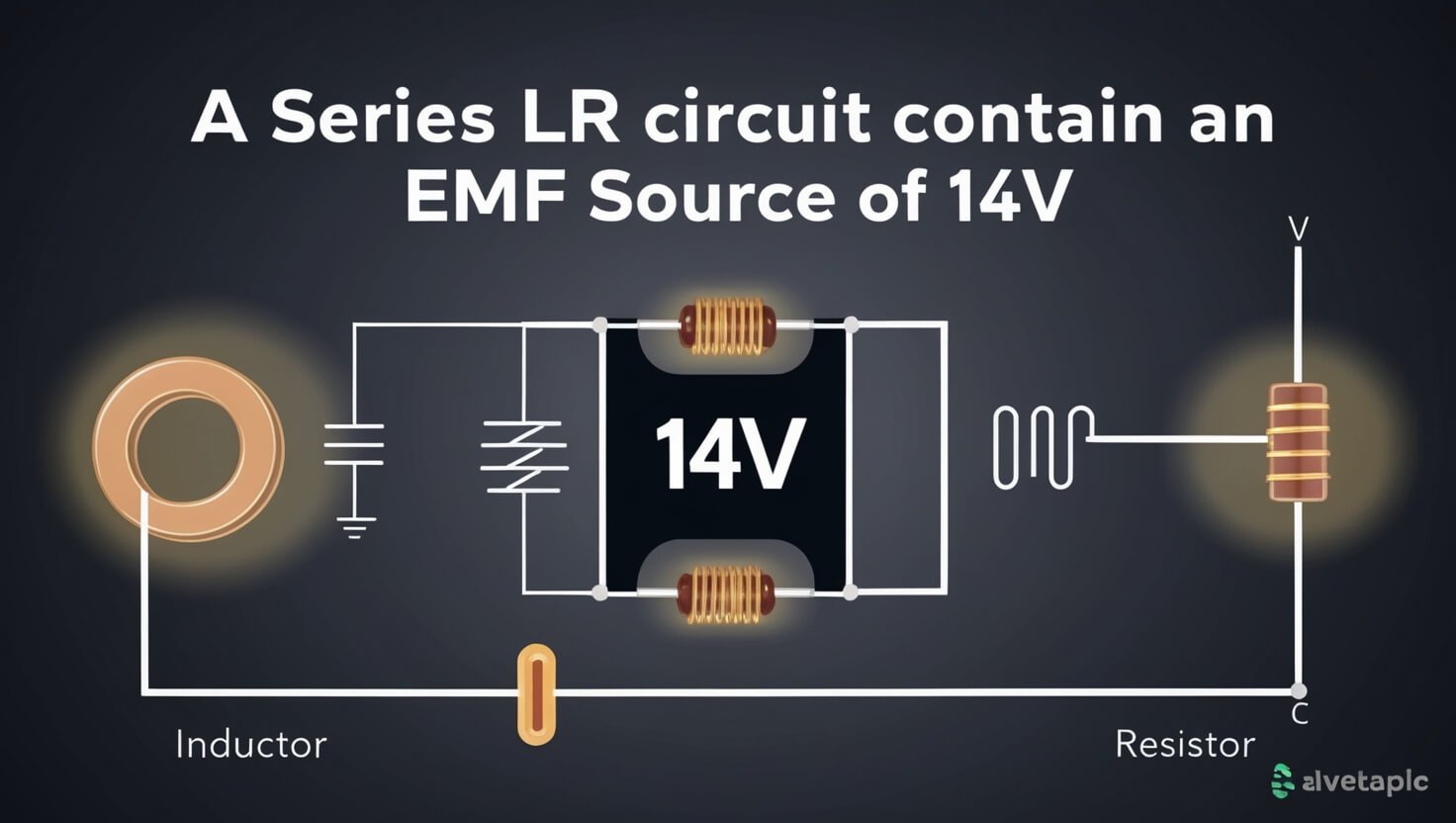
A Series LR Circuit Contains An EMF Source Of 14v
In a series LR circuit with a 14V EMF source, we’ll explore its behavior. We’ll look at the initial current, steady state, and overall response. This will help us understand how these parts work together.
Initial Current Behavior
When the circuit starts, the initial current is set by the 14V EMF source and the circuit’s resistance. The inductor will slow down changes in current. This causes the current to rise gradually over time.
Steady State Analysis
After the initial period, the circuit reaches a steady state. Here, the current and voltage stay the same. The voltage drops across the resistor and inductor balance out. This makes it easier to analyze the circuit’s behavior.
Circuit Response Characteristics
The circuit response to the 14V EMF source has both transient and steady-state parts. Knowing these is key to predicting the circuit’s behavior and ensuring it works right.
| Characteristic | Description |
|---|---|
| Initial Current | The current that flows right after the circuit starts, set by the 14V EMF source and the circuit’s resistance. |
| Steady State | The condition where the current and voltage in the circuit stay the same, with the voltage drop across the resistor and inductor balanced. |
| Circuit Response | The overall behavior of the circuit, including both the transient and steady-state parts, in response to the 14V EMF source. |
Mathematical Analysis of Current Flow
In electrical engineering, understanding current flow in series LR circuits is key. We use differential equations and other tools to dive deep into current flow dynamics. This helps us grasp how these circuits work.
Differential equations are at the core of this study. They show how current changes with circuit elements like resistors and inductors. Solving these equations lets us predict current flow at any time. This is crucial for circuit analysis and design.
Also, we can study the transient and steady-state responses of circuits. This is vital for circuit analysis and designing electrical engineering systems. It helps us understand how current changes over time and affects circuit performance.
| Mathematical Tool | Application in Current Flow Analysis |
|---|---|
| Differential Equations | Modeling the relationship between current, voltage, and circuit elements |
| Laplace Transforms | Analyzing the transient and steady-state responses of the circuit |
| Complex Number Analysis | Studying the frequency-dependent behavior of the circuit |
Using these mathematical tools, we can fully understand current flow in series LR circuits. This knowledge helps us design, analyze, and improve electrical systems more effectively.
Time Constants in LR Circuit Behavior
Exploring series LR circuits, we find time constants key. They affect how these electrical systems work. We’ll look at how to calculate them and their impact on circuit performance.
Calculation Methods for Time Constants
The time constant is the product of inductance (L) and resistance (R). This is shown as:
Time Constant (τ) = L / R
This formula helps us find the time constant for any LR circuit. Knowing this is vital for predicting how the circuit will react to changes. It also tells us how well it can store and release energy.
Impact on Circuit Performance
- Time constants affect how fast current and voltage change in LR circuits.
- Circuits with shorter time constants respond quicker, making adjustments faster.
- On the other hand, longer time constants mean a slower response. This can be good for smooth transitions or less electrical noise.
- The time constant also influences how well a circuit stores and releases energy. This affects its performance and efficiency in electrical engineering.
| Circuit Parameter | Shorter Time Constant | Longer Time Constant |
|---|---|---|
| Current and Voltage Response | Faster | Slower |
| Energy Storage and Release | Less Efficient | More Efficient |
| Circuit Performance | Suitable for rapid changes | Suitable for smooth transitions |
Understanding time constants in LR circuit behavior helps us improve our electrical systems. We can design them better to meet different circuit performance needs.
Energy Storage and Distribution
In series LR circuits, inductance is key for energy storage and distribution. It’s a basic concept in electrical engineering. It greatly affects how the circuit works and performs.
When AC flows through an inductor, it creates a magnetic field. This field induces a voltage that tries to stop the current from changing. This is called inductance. It lets the circuit store energy in a magnetic field.
The energy stored depends on the inductance and the current. The more inductance and current, the more energy is stored.
- The energy stored in an inductor is calculated by: E = 1/2 * L * I^2. Here, E is the stored energy, L is the inductance, and I is the current.
- To understand energy distribution in a series LR circuit, look at the voltage drops. Also, examine the phase relationship between current and voltage.
| Component | Energy Storage | Energy Distribution |
|---|---|---|
| Resistor | No energy storage | Dissipates energy as heat |
| Inductor | Stores energy in magnetic field | Alternates between storing and releasing energy |
Understanding energy storage and distribution in series LR circuits is vital. It’s important for electrical engineering like power systems and motor control. By studying inductance, engineers can make better electrical systems.
Power Calculations and Circuit Efficiency
In electrical engineering, knowing how to calculate power and improve circuit efficiency is key. This is crucial for making series LR circuits work better. Let’s explore the main points of this topic.
Real Power Analysis
Real power, or active power, is what the circuit actually uses to do work. To figure out real power, we look at voltage, current, and their phase angle. The formula is: P = VI cos(θ). Here, P is real power, V is voltage, I is current, and θ is the phase angle.
Studying real power helps us see how well a circuit works and where it can get better. By boosting real power, we can make the circuit perform better and save energy.
Power Factor Considerations
- Power factor shows how well a circuit uses available power.
- It’s the ratio of real power to apparent power, and it’s between 0 and 1.
- A power factor close to 1 means a circuit is more efficient. This is because more apparent power is turned into real, useful power.
- Boosting the power factor can cut down energy use, lower costs, and make systems more reliable.
Getting the hang of power calculations and working on power factor, we can make our series LR circuits more efficient. This leads to better performance and cost-effective solutions in electrical engineering.
Practical Applications in Electrical Systems
Series LR circuits with a 14V EMF source are used in many electrical systems and engineering fields. They are key in circuit analysis and electrical engineering. This makes them very useful in different industries.
In power supply design, these circuits help regulate and stabilize voltage. Engineers use them to make efficient power units for many devices. This includes everything from home appliances to big industrial machines.
Series LR circuits are also crucial in motor control systems. The inductor helps control motor speed and torque. This is important for devices like servo motors and variable-speed drives.
| Application | Key Benefits |
|---|---|
| Power Supply Design | Voltage regulation and stabilization |
| Motor Control Systems | Precise speed and torque control |
| Electromagnetic Braking Systems | Smooth and efficient braking |
| Filter Circuits | Noise reduction and signal conditioning |
Series LR circuits are also used in electromagnetic braking systems. They help create smooth braking. These circuits are also in filter circuits, where they reduce noise and improve electrical signals.
Series LR circuits with a 14V EMF source have many uses. They are vital in electrical systems and electrical engineering. They are a key part in designing and running many electrical systems and technologies.
Bottom Line
We’ve explored series LR circuits with a 14V EMF source. We now understand the basics and the complex math behind them. These circuits are key in electrical engineering.
We’ve learned about the parts of the circuit and how current flows. We’ve also seen how time constants affect performance. This knowledge helps us design and fix these circuits for different uses.
Our study of series LR circuits with a 14V EMF source is complete. We’re ready to apply what we’ve learned. This will help us solve complex problems and improve electrical technology.


