As electrical enthusiasts, we understand the need to keep our circuits working right. A digital multimeter is key for this, as it can check many electrical things, like continuity. Checking for continuity helps find electrical problems and makes sure connections are good.
We’ll show you how to use a digital multimeter to check for continuity. This will help you fix and keep your electrical systems running smoothly.
Digital multimeters are great for checking electrical connections. They send a small current through probes and measure the resistance. Knowing how to use these tools helps spot problems like bad connections and short circuits.
These skills are useful for many things, like fixing home appliances, car wiring, or even paper circuits. Learning to test continuity with a digital multimeter is a must for anyone interested in electricity.
Basic Components of a Digital Multimeter
Digital multimeters are handy tools for checking circuits, batteries, and fixing electronics. They have a digital screen for clear readings and buttons or a dial for different tests.
Display and Control Panel Features
The digital screen on a multimeter makes it easy to read measurements. It’s great for everyday use and getting accurate results. You can switch between tests like AC voltage, DC voltage, and resistance with the control panel.
Terminal Ports and Their Functions
Multimeters have ports for the test probes. The common (COM) port is for the black probe, and the V/Ω port is for the red probe. Some models also have extra ports for more tests.
Probe Types and Applications
The probes that come with a multimeter are made for specific jobs. Needle-tipped probes fit into small spaces, and alligator clips make testing easier without holding the probes. You can also get accessories like Banana to Alligator Cables and Multimeter Probes – Needle Tipped to make your multimeter more versatile.
| Product | Price | Favorites |
|---|---|---|
| SparkFun Digital Multimeter | $16.50 | – |
| USB Power Meter (Color TFT LCD) | $26.95 | – |
| Smart SMD Tester | $29.95 | 24 |
| USB Digital Multimeter – Auto-Ranging (RS232 Output) | – | 33 |
Safety Precautions Before Testing
When using a digital multimeter, electrical safety is key. Always make sure the circuit is off by unplugging devices or turning off power. Also, wait for any capacitors to fully discharge, like in hot tubs or car electronics.
Wearing the right personal protective equipment (PPE) is vital. Follow the manufacturer’s advice and use insulated gloves and eye protection. This helps prevent electric shock and other dangers. It’s also important to test the multimeter’s probes against each other before starting.
- Ensure the circuit is de-energized and capacitors are discharged before testing
- Use appropriate personal protective equipment (PPE) as recommended by the manufacturer
- Test the multimeter probes against each other to verify functionality before use
| Safety Metric | Minimum Recommendation | Ideal Recommendation |
|---|---|---|
| Multimeter CAT Rating | CAT III | CAT IV |
| IP (Ingress Protection) Code | IP54 (Dust and Splash Proof) | IP68 (Dust and Water Tight) |
| Fuse Rating | 600V | 1000V |
“Proper safety precautions are essential when using a digital multimeter to avoid electrical hazards and ensure accurate measurements.”
Following these safety tips, we can reduce risks in electrical work. This ensures a safe and successful continuity testing experience.
Setting Up Your Multimeter for Continuity Testing
To accurately check for continuity, you need to set up your digital multimeter right. Let’s go through the important steps to get reliable results.
Selecting the Correct Mode
First, find the continuity mode on your multimeter. It’s usually marked with a diode or sound wave symbol. If there’s no specific mode, use the lowest resistance setting, like 200Ω or 2kΩ.
Calibrating Your Device
Before you start, calibrate your multimeter by touching the probes together. This makes sure it’s working right. A reading close to zero or a beep means it’s calibrated. Some multimeters need manual calibration or zeroing before use.
Testing the Probes
After calibrating, test the probes by touching them together. You should see a zero reading or hear a beep. This confirms your multimeter is ready for continuity testing. If not, check the probes and the multimeter settings.
These steps will help you properly configure your digital multimeter to test for electrical continuity in your circuits and components.
How To Check For Continuity With A Digital Multimeter
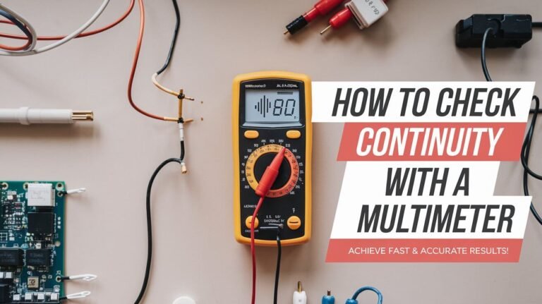
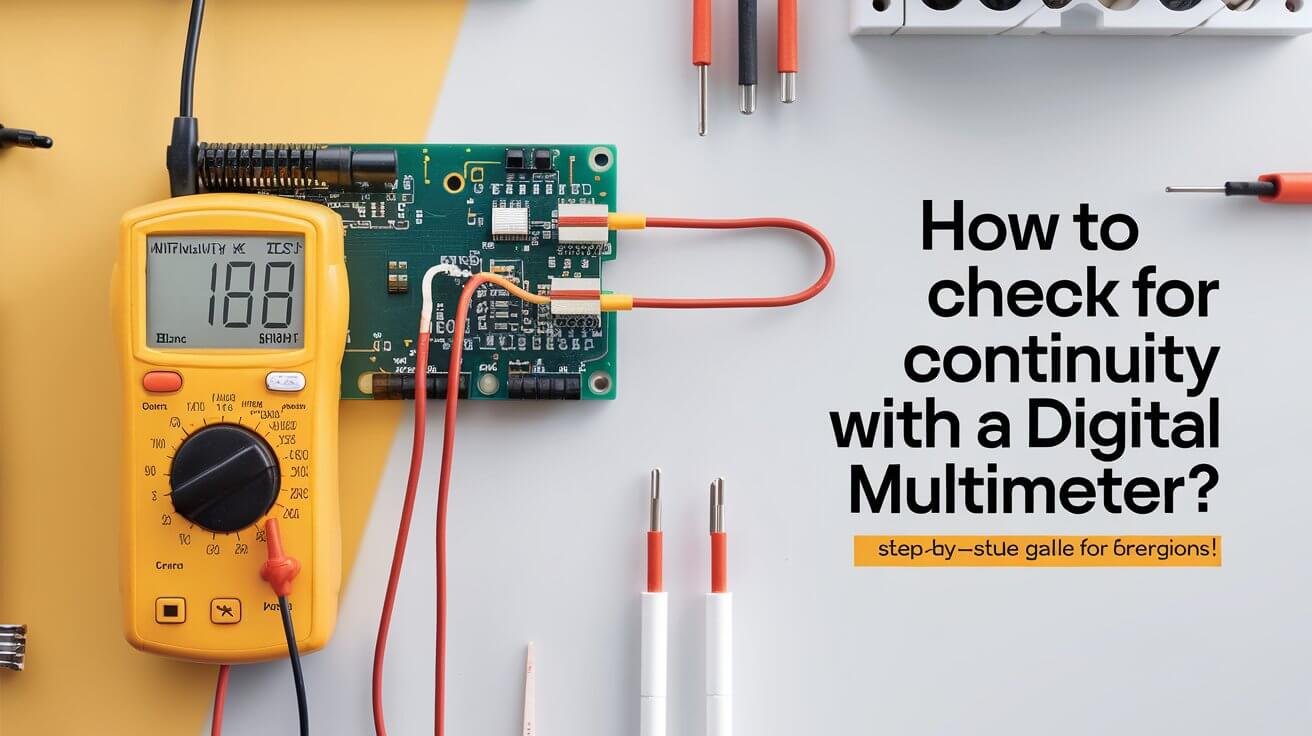
Checking for continuity is key in electrical diagnostics. If you think there’s a fault in a circuit, a digital multimeter can spot it fast. It sends a small current and checks the resistance to see if electricity can flow.
To check for continuity with a digital multimeter, follow these steps:
- Make sure the circuit’s power is off before you start. This step prevents damage to your multimeter.
- Switch your multimeter to the continuity or resistance mode. Look for the radio wave symbol.
- Put the black probe on one end and the red probe on the other of what you’re testing.
- For wires, test from end to end. For switches, test both on and off positions.
If the circuit is continuous, the multimeter will show a reading close to 0 ohms or beep. This means current can flow freely. A high resistance or no reading at all means there’s a break that needs fixing.
| Continuity Reading | Significance |
|---|---|
| 0 ohms | Perfect continuity |
| Less than 1 ohm | Good continuity or dirty terminals |
| 1-10 ohms | Consult device manual for guidance |
| Higher than 10 ohms | Poor continuity, replace component |
| No reading | Broken circuit, check for faults |
Continuity testing is great for many tasks, like checking solder joints and verifying blown fuses. Knowing how to use your digital multimeter for continuity testing helps you fix electrical issues fast.
Reading and Interpreting Continuity Test Results
When you use a digital multimeter for continuity tests, it’s key to know what the readings mean. Understanding these results helps you find and fix electrical problems well.
Zero Reading Significance
A zero reading means the circuit is perfect. It shows the resistance between points is almost zero. This means the circuit works well.
High Resistance Readings
Readings of 1 to 10 ohms usually mean good continuity. But, the exact value depends on the device. Check your multimeter’s manual for what’s okay. If it’s over 10 ohms, there’s a problem.
Error Messages and Troubleshooting
- No reading or an “OL” (overload) message means the circuit is broken. This stops current flow.
- Strange readings or error messages can point to bad connections or damaged parts.
- If you see odd readings or errors, check your connections and the circuit’s integrity. This helps find and fix issues.
Knowing what multimeter readings mean helps you understand test results. This knowledge lets you fix electrical problems in your projects.
Testing Electrical Wires and Cables
Testing the continuity of wires and cables is key in electrical diagnostics. A digital multimeter is vital for this task. It helps us check if electricity flows well through our circuits. This tool lets us spot any breaks or shorts in the wiring, keeping our electrical systems safe and working right.
To test a wire or cable, just put the multimeter’s probes at both ends. For cables with many wires, test each one separately. Make sure the probes touch bare metal for a correct reading.
- A low resistance reading means the connection is good.
- To find shorts in multi-conductor cables, test each wire against others. We should see no connection unless it’s meant to be.
Following this troubleshooting process will help identify and repair electrical wiring issues, ensuring your home or workplace remains safe and properly functioning.
| Test | Desired Outcome | Significance |
|---|---|---|
| Wire Continuity | Low Resistance Reading | Indicates an unbroken, continuous connection |
| Check for Shorts Between Wires | No Continuity Between Conductors | Confirms proper insulation and no unintentional connections |
“Continuity testing is a crucial step in ensuring the safety and functionality of our electrical systems. By using a digital multimeter, we can quickly identify any issues and take the necessary steps to maintain a reliable and efficient electrical infrastructure.”
Checking Fuses and Circuit Breakers
As homeowners, we often face electrical issues at home. We might need to test fuses and circuit breakers. A digital multimeter helps us check these devices quickly and accurately. This ensures our electrical systems are safe and work well.
Common Fuse Testing Methods
Testing a fuse with a multimeter is easy. Just put the probes on the fuse body, making sure they touch both ends. If the fuse is good, the multimeter will show a low resistance or beep. A bad fuse will show an “OL” or infinite resistance.
Circuit Breaker Verification Steps
- Set your multimeter to the right voltage range, like 120V or 240V, based on your home’s system.
- With the breaker on, test between the input and output. You should see a voltage close to your home’s rated voltage, showing the breaker works.
- Then, turn the breaker off and test again. The multimeter should show an “OL” reading, meaning the breaker has cut the circuit.
- If the breaker doesn’t act right, it might be bad and need replacing. Check the maker’s guide for how to test it, as some need special steps.
| Electrical Protection Device | Voltage Rating | Safety Precautions | Resistance Measurement |
|---|---|---|---|
| Fuse | Based on circuit requirements | Turn off the main breaker before testing | Continuity test (low resistance) |
| Circuit Breaker | 120V or 240V | Use insulated gloves and safety glasses | Measure resistance in “on” and “off” positions |
If you’re not sure how to test or have problems, get a licensed electrician’s help. It’s key to check fuses and circuit breakers right to keep your home’s electrical system safe and reliable.
Examining Switches and Outlets
A digital multimeter is key for fixing electrical issues. It’s great for checking switches and outlets. Let’s look at how to use it for these tasks.
Switch Testing
To test a switch, we check its terminals in both positions. A good switch shows continuity (low resistance) when on and no continuity (high resistance) when off. This confirms it works right.
Outlet Diagnostics
Testing an outlet’s continuity is crucial. We check between hot and neutral, hot and ground, and neutral and ground. The right wiring means continuity in these spots, showing the outlet is safe.
Always turn off power before testing switches or outlets. Safety is the most important thing when dealing with electricity.
“A digital multimeter is an essential tool for any electrician or DIY enthusiast. Its ability to test switches, outlets, and a wide range of electrical components is invaluable in diagnosing and troubleshooting issues.”
These circuit testing procedures will help you diagnose electrical problems, whether you’re dealing with minor repairs or more complicated electrical issues.
Testing Electronic Components and Circuit Boards
Diagnosing and troubleshooting electronic circuits is key. We must isolate components and check circuit paths. Our digital multimeter helps us do this well.
Component Isolation Techniques
To test components like diodes and resistors, we isolate them first. We disconnect them from the board. This lets us measure their behavior without circuit interference.
Circuit Path Verification
Checking circuit paths on PCBs is vital. Our multimeter’s continuity function helps us. It ensures connections are good, spotting any breaks or shorts.
Testing components and boards requires care, mainly with sensitive parts. We use low voltage settings to avoid damage. This keeps delicate electronics safe.
Quick Answers
What is the purpose of continuity testing with a digital multimeter?
Continuity testing finds breaks in circuits and faulty connections. It’s key for fixing electrical issues in devices and systems.
What are the basic components of a digital multimeter?
Digital multimeters have an LED display and a dial for choosing functions. They also have ports for probes. The black probe goes into the COM port, and the red probe into the V/Ω port for continuity tests. Some models have extra ports for high current tests.
What safety precautions should I take before testing for continuity?
Make sure the circuit is off by unplugging or turning off power. Wait for devices like hot tubs or cars to discharge. Always wear the right safety gear and follow the manufacturer’s instructions.
How do I set up my digital multimeter for continuity testing?
Switch to continuity mode, shown by a diode or sound wave symbol. If there’s no continuity mode, use the lowest resistance setting. Check the device by touching probes together; a near-zero reading or beep means it’s working right.
What is the process for checking continuity with a digital multimeter?
Put the black probe on one end and the red probe on the other. A near-zero reading or beep means it’s connected. High resistance or no reading means there’s a break.
How do I interpret the results of a continuity test?
A zero reading means it’s perfect. Readings under 1 ohm are good, while 1-10 ohms might be okay. Over 10 ohms is bad. No reading or error messages mean it’s broken.
How can I test wires and cables for continuity?
Test wires by placing probes at both ends. For cables with many wires, test each one. A low reading means it’s connected well. Testing between wires can find shorts.
How do I check the continuity of fuses and circuit breakers?
For fuses, test both ends. A good fuse will show continuity. Circuit breakers should show continuity when on and none when off.
How can I use continuity testing to examine switches and outlets?
Test switches in both on and off positions. A good switch shows continuity when on and none when off. Outlets should show continuity between certain terminals.
How can I use continuity testing to diagnose issues on circuit boards?
Isolate components on circuit boards by disconnecting them. Test each part like diodes and resistors. Use continuity to check connections on the board.

